Why I don’t use the Bash Shell anymore

As I am using Linux and the terminal more and more I came across some annoyances and limitations of the default bash terminal in Ubuntu and OSX. In this article, I will describe how discovered what I am missing in the default terminal and how I learned how to overcome the shortcomings of bash with some simple and more complex extensions and tools.

Terminal Window multiplexer

Even for simple tasks, it is very often necessary or at least helpful to open more than one terminal window at once. For example when you need to make changes to a configuration script in nano or vim in one terminal and run the execution in another one. Or when you want to run one server script in one window and a client script in a second one. I needed to do this kind of tasks often enough to be annoyed by the fact that I have to open several windows just to run commands at the same time. My first try for solving this was using the terminal emulator Terminator . With its shortcuts and context menus, you can solve this problem by splitting a terminal session horizontally and vertically several times.

Bildschirmfoto 2018-07-20 um 01.08.59.pngTerminator has the advantage as well that you can change the color profile with lots of presets and you can use your mouse cursor to change window sizes. This is a very common solution to the above discribed problem in the Linux world. The caveat for me as an OSX and Linux user is that Terminator is not cross-platform. There are similar tools for OSX like iTerm2 but it uses different shortcuts for splitting windows again, which makes it a mess changing systems several times a day. Still, its a very good tool and several advanced features compared to the default OSX terminal.

I use both iTerm2 and Terminator for lots of there features but not for splitting windows. What I found to be my tool of choice is tmux as it runs directly in one terminal window and can therefore also be started in a ssh session from the remote machine without starting several ssh connections.

Bildschirmfoto 2018-07-20 um 01.25.27.png

Tmux is a great tool if you like shortcuts a lot. Otherwise, you will get frustrated quickly as tmux is fully controlled by your keyboard. This can definitely also be called its strong point, as your hands don’t need to leave the homerow. As I am using a German keyboard where the default shortcuts of tmux are a lot harder to use than on an English keyboard I changed mine to be more friendly combinations.

  66 # split current window horizontally
  67 bind - split-window -v
  68 # split current window vertically
  69 bind _ split-window -h
  70
  71 # pane navigation
  72 bind -r h select-pane -L  # move left
  73 bind -r j select-pane -D  # move down
  74 bind -r k select-pane -U  # move up
  75 bind -r l select-pane -R  # move right

All my shortcuts start with a CMD + A combination. As the CMD key is not on the home row, I changed my Caps lock key to an additional CMD key. This helps a lot in typing and navigating speed and I really don’t need the Caps lock key anyway. In OSX you can do that with the system settings and in Ubuntu, the Gnome Tweek tools can do that.

One more quick tip is to change the default key registration and repeat speed of your keyboard to something a lot quicker. By doing that your pc feels so much faster and navigating the terminal is lots faster. cursor-key-featured-cropped

In addition to this configuration, you can do lots more which helps to make tmux more feature rich and nice looking.

Everything Bash can’t do

Bash can be a very quick tool when you know how to use it and watch some YouTube videos on useful tools and tricks or follow Julia Evans on Twitter to learn new stuff in small comic style like cards. Still, you will find after a while that some fundamental functions are missing which will be frustrating in the long run.

This is where zsh and the community-driven framework oh my zsh comes to the rescue. Zsh (spoken C shell) is basically a replacement for the default Bash and can be installed simply via apt-get.  Zsh gives you advanced features like auto-completion for commands, path, and arguments in commands without being case sensitive. Bildschirmfoto 2018-07-20 um 02.21.41.png

By tapping your way through the options you can navigate through your folders and arguments without having to type more letters as you do in Bash. Zsh in combination with oh my zsh has so many features, plugins and options that I would need to write an article alone.

Final result

tmx_zsh.png

Very soon after installing the mentioned tools, you will discover all the possibilities on your own and love them, but hate all the options and time they need for understanding😅. I definitely don’t regret spending a fair amount of time on my configuration and am pleased with all the time and frustration I am saving now on a daily bases.

X-mas Tree

img_3278

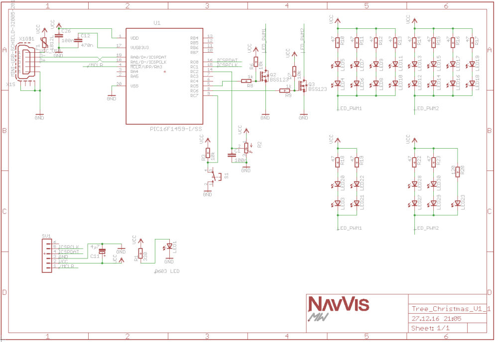
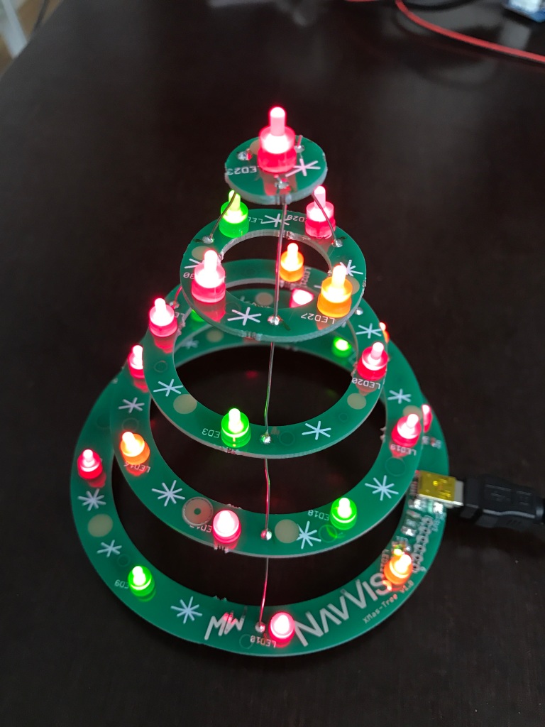
As it is Christmas time and I wanted to do a simple, cheap and fun project, which works as a development board at the same time, I created this X-mas tree.

img_3276

The project features an USB capable PIC16F1549 µC with:

  • USB FS device
  • 48 MHz internal Oscillator
  • 2 PWM modules
  • 10-bit ADC with Voltage Reference
  • Integrated Temperature Indicator Module

The LEDs are connected to the 2 PWM outputs via N-mos drivers. A Potentiometer is connected to one ADC channel for controlling the brightness of the LEDs or possibly the speed or variation of animations. Different modes of the X-mass tree can be switched by pressing a push button.

Schematic / Layout

Schematic

The schematic shows that the µC is directly connected to USB. This is definitely bad practice, as the µC has no ESD protection. In several other projects I used a SOT23-6 USB ESD protection diode array and sometimes two additional serial resistors.

A 500mA Fuse F1 was added to protect the PC or power supply in case of a short circuit our failure. This will be an important step, as the X-mas tree will be used for a soldering workshop for working students and  anybody interested in electronics hardware or embedded software at my new job at NavVis in Munich (therefore the NavVis logo on the PCB).

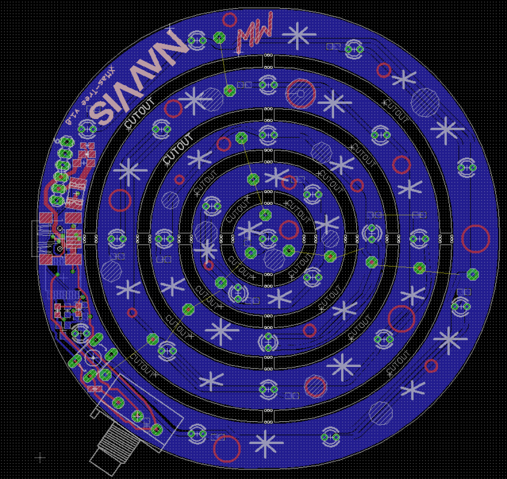
The Layout is designed for two different levels of soldering skills. It features a TSSOP IC, a SMD USB connector and some 0603 resistors and capacitors for the skilled and through hole LEDs for soldering beginners.

Ordering the PCBs is quite cheap as all the 5 parts of the X-mas tree are on one 10×10 cm panel and can be bought from DirtyPCB for just 15USD.

bildschirmfoto-2016-12-27-um-22-13-33

Software update

For using the tree as a simple software development board it must be possible to use it without an InSystemProgrammer like the PICkit3. As the µC already uses an USB connection to the PC it makes sense to use a Bootloader for updating the program code. The code area is only 8K (words) and a full USB stack for the Bootloader takes up already 50% of it. Nonetheless it fits and there is still enough space for some blinky LED code ;).

Here is some code for controlling the Tree:

GitHub XmasTree

Upgrading my Bose QC25 Headphones with Bluetooth BLE (Part 1)

Well, I didn’t really write a blog post in a long time now… after dangerous prototypes and HACKADAY featured my blog I was kind of stoked with all the great responses! Thanks a lot for that! While that time I was also on a semester abroad in Malaysia doing some multi core embedded systems courses with focus on reliability. There I was digging a lot deeper into 8052 and ARM Core structures as well as more exotic ones like the XMOS cores. But now finally I am back – relocated to Munich for my master thesis – finding more time doing some nice electronics projects and writing about it.

Here it starts


I own a paar of Bose QC25 headphones for about a year now and it was a tough decision to make if you are a maximizer as I am. The main factors I considered were

  • Sound quality
  • Noise canceling
  • Bluetooth support (aptX if possible)
  • Play/Pause/Vol+-/Next/Prev Buttons

Long story short. The Sennheiser MM 550X’s sound quality was just ridiculous for the price, the audio technica M50X had really great audio quality not only for the small price but had a lack of all the other features and the AKG K550’s sounded reasonable but couldn’t hold up against all the features and quality of the Bose QC25.

So the QC25 (Quiet Comfort) feature good sound with and without batteries and do a perfect job with canceling any background noise. But… and thats the point of this blog… they do not have Bluetooth support. And I am about the change that.

Cheep BLE modules with all kinds of functionality are so cheep nowadays ready to get prototyped right form all these chines Web shops. I ordered 2 different modules to check them out without having the full plan on how everything should fit together. As I knew I needed some parts for sure, my first shopping cart looked like this:

  • 150mAh LiPo link
  • 240mAh LiPo link
  • Bluetooth 2.0 Audio module link
  • USB LiPo charger module link

I built the prototype by connecting one of the LiPo cells up to the charger and connected that then to the Bluetooth module which worked first go. The range was quite good and even stuffed inside my headphones with the metal shielding they work great. I had some issues with additional noise but I could have fixed these by decoupling. However I didn’t because the power consumption of this Bluetooth 2.0 module was with using about 56 mA just to high. So I had to switch to a BLE (Bluetooth Low Energy) module, to do what it says – use lower energy -.

Bluetooth2_0 module

In fact it did just that so that the battery should theoretically last far more then 15h which should be alright with a typical use. But I experienced some major problems with an ultra low range of just under 50cm without interruptions. that means with my phone in my pocket and the headphones on a simple move of my hand to my head will interrupt the playback and will ruin the experience… My plans for that is to try using different antennas maybe one which was designed for the ESP8266 Wifi module as it should also be trimmed for the 2,4GHz band or moving the module further away from the metal shielding inside the headphones. But… this is the point where I am right now.

Some inside views of the QC25

My plans with this project should not stop there. What I actually want to do is bringing this to the next level. I am planing on using a MSP430 ultra low power microcontroller to add some touch gesture recognition on the surface of the headphones to control the volume, play/pause, next/prev and possibly some more features. Also I want to add a microphone as the one built in the stock cable will not be used after the modification (as well as the buttons there). It sounds like fun to me and maybe you own a paar of those headphones too and join me on the mod.

Crane controller assembly (DirtyPCB boards)

A month ago I wrote about the update for the crane controller board. There I talked about the advantages of „professional“ ordered PCBs over milled PCBs without solder mask. As I discussed, for me dirtyPCB wins in terms of price and quality in the context of a hobbyist/semi professional project. So I ordered my 100×100 mm protopack (~10 PCBs) boards there for 25$. I also added an extra 16$ for fast shipping with DHL China.

KranPower DirtyPCB

The great think after placing your order is, that you now can see a rendered version of your PCB design

KranPower DirtyPCB render

And as soon as you see the first submitted file… you know you want to change or fix something. Even though you’ve seen your design in eagle, a rendered version will give you an significantly better impression of what the actual board will look like. In my case I added a lot of values for some components, little notes and markings to the silkscreen, to make it easier to assamble the board once it arrives. And sooner or later the order info for your boards may look like this.

Order Info

But that’s the great think with dirtyPCB. They allow you to change and upload now versions of your board file until it gets sent to the board House. And in my case I uploaded 4 new versions of my file.

From this Order info you can see the timestamps as well. I submitted my board the first time on the 10th of april. Two days later dirtyPCB sent it to the board house. Another 7 days later it got back and was shipped to me. Or I think what really happens is, that the boards are given to the shipping company which then shipped my boards on the two days later. Overall it took 11 days from my .brd file till the PCBs where shipped. And thanks to DHL I received my boards on 23rd of April.

DirtyPCB claims that their boards are crappy, which is not true in most cases, I think. At first glance, my boards look good and except from a view scratches on one board there where no problems with them. But when I took a closer look while assembling the boards, I quickly noticed some strange changes that where made to my design. I used big octagon pads for the step down daughter boards and they where somehow rotated by 22 degree. Even weirder was that fact that the spacing around the pad was not rotated as you can see in the picture below.

dirtyPCBocta

The spacing between the pads and the ground layer isn’t to great now but as there aren’t any shirt circuits I’m not going to complain to much. I wrote Ian from diryPCB/dangerousPrototypes to inform them about the problem and hopefully they can find and fix the bug in there gerber export.

Nevertheless I was quite happy with the overall quality of the boards so I immediately started assembling the crane controller. I took a time-lapse video of the soldering and the first test of the board, which worked out great.

I hope you like the video and it’s not to boring. If you want to order this board form dirtyPCB you can use the link below.

Buy KranPower

POI light toy

At the moment I am teaching a class in collage where the students use CC430 microcontrollers to learn the basics of wireless sensor networks. This class is more like a practical training with a few lessons to teach the theories behind it and explain some of the peripherals of the controller and the RF stuff. The course is structured in 3 parts and each part consists of 3 lessons. Bildschirmfoto 2015-03-31 um 12.03.32

The problem with that is, some students are faster then I expected with finishing the tasks for part 1. So I had to come up with an extra task for part 1. In the task of part 1, the students got taught how to use Flash memory, the UART interface and the SPI bus. The board which is used in the practical training happens to have an SPI port expander with 8 LEDs on it. Thus it is perfectly suitable for a POI light toy. Watch the YouTube Video if you want to see some of this devices in action.

Bildschirmfoto 2015-03-31 um 12.09.57

This type of art works by capturing the movement of the leds with a camera set to long exposure. While moving the led device, the led patterns will change and draw some colors or text. In my case I implemented a simple „Hello World!“ text to prove the concept.

IMG_1703

The job for the students is to write some code which can read a text from the serial interface, store that data in flash memory and show the text on startup via the leds on the port expander. So it is a combination of all the newly acquired skills in one project.

Provided for that will be a 5×8 character array in form of a .h file and a simple Spi library for sending out data. Hopefully it takes at least one course date (~3 hours) for the students to figure out how to do that, to keep them busy till part 2 of the course.

As the code is really short I will post it right here. You will find the project as always on Github

// POI
#include "drivers/spi.h"
#include "defines.h"
#include "font.c"</code>

char msg[] = "Hello World! ";
uint8_t len = 14;

void printChar(char c);

void send_Byte(char add, char data){
  SPI_OUT_PORT &amp;= ~CS_PIN;
  spi_send(0x40);
  spi_send(add);
  spi_send(data);
  SPI_OUT_PORT |= CS_PIN;
}

void main(void){
  WDTCTL = WDTPW | WDTHOLD; // Stop watchdog timer
  initSPI();

  send_Byte(0x01, 0x00);

  while(1){
    int i=0;
    for(i=0;i&lt;len;i++)
      printChar(msg[i]);
  }
}

void printChar(char c){
  int i=0;
  for(i=0;i&lt;5;i++){
    int line = font[(c*5)+i];
    send_Byte(0x13, line);
    __delay_cycles(500);
  }
}

Github: POI_light_toy

Crane controller UPDATE

Last december I posted a blog about the development of the crane controller. The controller is working fine, most of the time… but because of the eararsh conditions and the moisture some errors occurred.

If you haven’t already read the post about the crane controller, you can use this link to know the background about this story: Crane controller Dez2015

A big potential for faults is the fact that the pcb was made with a mill and not properly etched. This results in problems with oxidation of the traces. The vias between the top and bottom layer were implemented with copper rivets. This rivets typically build a electrical connection just by the force of the squeezing. But to ensure a longtime connection it is essential to solder all the vias after riveting. Still there is a high risk of failure due to vibrations and the non professional designed vias.

nieten

At the time two of this vias caused errors on the controller and the power board.

The second big point is the lack of solder resist on the pcb. With time the moisture in the plastic case will oxidize the copper resist and slowly build electrical bridges between tracks. This produces problems with signal integrity which can be observed in form of display faults and pixel/color problems. As the spi bus is already over its maximum length with 10 meters – which could only be achieved by using a differential receiver/transmitter – the signal integrity is a very important point.

All this potentials of faults can be eliminated by using a proper 2 layer pcb with a solder resist layer. As this pcbs are not cheap in the context of a hobby project I had to look for cheap alternatives to regular board houses here in Germany. As always: China shops are a hobbyists best friend! For example Dirt Cheap Dirty Boards is one of the cheapest board houses with free international shipping. You will get ~10 pcbs in 50x50mm for 14 USD or 100x100mm for 25 USD. If you do not need that much boards you can also use a service from the US. It is called OSH Park and you have probably seen some projects with the iconic purple solder resists. This service charges you by the area of your pcb so that you will pay $5 per square inch and always get 3 copies of your board. Depending on your needs you will always make a good deal with one this board houses. The quality is by no means as good as with a regular board house from the US or Germany, but it should be good enough for all hobby projects.

osh_leftdirty_right

As the prices for pcbs larger than 100x100mm go up significantly, I decided to do a redesign of the KranPower pcb. The schematic has only been updated minor. I just layed out the board on the smaller area and resigned of the cutouts for better heat diffusion of the step down regulators. This cutouts turned out to be obsolet, as the temperature of the regulators won’t rise above 45°C. By making that changes it wasn’t to hard to shrink down the size to the maximal area of the 25 USD pcbs from DirtPCB.

Taking the chance of a redesign to make some changes to the schematic too, I added some components and functionality. One thing was the DVI connector. I used a 90° version this time to avoid bending the cable and its connector to fit it into the case. I also added a reverse protection diode right after the screw terminal. It is a 30 amp high power version as in some situations all the servo motors can draw their peak current.

Bildschirmfoto 2015-03-31 um 01.00.05

The software also got a little update. I implemented a low pass filter for smoothing the movements of the crane and improve the safety of the hole system by that. By reducing the maximum acceleration of the crane, the risk of flipping the tractor over can reduced significantly as well.

#if defined(LP_FILTER)
    //Low Pass Filter
    ain[i] = ((LP_coeff * ainOLD[i] + (10 - LP_coeff) * ain[i]) / 10);
    ainOLD[i] = ain[i];		//store old value
#endif

This C code is one of the simplest forms of a first order low pass filter with just one filter coefficient.

All the updated files can be found on Github:

GitHub: KranSteuerung V7.0
Eagle files: KranPower V2.1

Automated test jig

As I am currently working on a project with 100 nodes for a wireless sensor network (WSN), I needed a way to program this devices in a fast and easy way. For that propose I started developing a half way automated test jig which will help test, program and verify the prober function of the nodes.

Bildschirmfoto 2014-08-07 um 22.16.34

This jig uses a clamping mechanism with pogo pins for contacting some test points on the WSN node. This nodes work in a wireless sensor network and consist of a CC430 microcontroller, a micro SD card holder and an H-bridge. As it is not practicable to plug in each board, insert the SD card and connect the battery, I developed this test jig to speed up this process.220px-Federkontaktstift.svg
Pogo Pins use spring loaded needles for ensuring a proper connection to the surface. This surface will be a test point or a specific area on the pcb.


The second part of the project was to write a pc client software to start and analyze the flashing and testing process. Therefor I developed a VB.net program with a graphical interface. This program takes use of the MSP430Flash tool which is a free to use command line program. Bildschirmfoto 2015-03-25 um 22.04.46

You can find the Software as well as the code on Github.
GitHub: FlashTool
Eagle files: NodeNadel

Crane controller

Bildschirmfoto 2014-08-08 um 13.16.02
Playing with development boards, some cool displays and stepper motors is always fun, of course. But what’s even nicer is controlling a real mechanical hardware thing. Like in my case, a hydraulic crane for forest work.

The concept of this project was to change or modify the old manual hydraulic valve box so that you can use joysticks to control the crane from the tractors cab. By moving the hand gear of each valve with a small but very strong servo motor, it was possible to control the crane from a distant position and over from the cabin.

Bildschirmfoto 2014-10-30 um 21.55.16

In this block diagram you can see the two parts of the controlling system. On the left there is the KranPower part which houses the microcontroller (Arduino ProMini), 6 of the shelf StepDown converter modules for 6 servo motors, 6 current shunts (INA138) plus a 8ch ADC (MCP3008) for measuring the current consumed by each servo, a johnson counter (74HC4017) for generating the PWM signal for the servos, RS422 transmitter (AM26LS31) and a Relay for shutting down a main valve in case of an emergency.
On the right side you can see the KranControl unit with a RS422 receiver (AM26LS32), a 1,8 inch TFT display, 2 three axes joysticks with buttons and a emergency switch.
The two parts are connected via a DVI cable, which is used because it is made for transmitting differential signals as I do with my SPI signal. This is necessary in the first place because it is just not possible to transmit a SPI signal with up to 4 MHz clock speed over 10 meters with steep enough edges. The cable length in combined with transmition speed is the problem. As I can’t decrease any of those two factors, I had to convert the SPI signals to a differential pair which is more or less described with RS422 and convert it back to a standard SPI right before I use the signal for the TFT display.

The Software for this project was written in C/C++ for an Arduino pro mini. Most of selected components are off the shelf parts so it was not to hard to find some easy to use libraries. One interesting part was the Display updating routine, as all of rendering runs in the main loop as well as the servo updating. To ensure smooth movements of the crane, the update rate must stay at least at about 20 fps (frames per second / servo updates per second).

Bildschirmfoto 2014-12-13 um 18.14.30

The picture on the right should show you how to update the pixels efficient so that you can achieve a significant speed boost. The first bar shows 3 green pixels out of 6 pixels total. If we want to update this bar to look like the second, we can write some simple for loop to print 6 new pixels. The second bar shows 6 new pixels, but as you can see at the third bar we only need to update 1 pixel to get the same result.
The code for that kind of update routine needs at least 10 times the effort to write and debug your code, but results in a performance boost of times 4. So we can achieve a update rate of 30 – 50 fps. The this simple routine as shown before we could at maximum get 8 – 13 fps.

You can find all the hardware designs, C/C++ code and a Power Point presentation on github and the links down below.

GitHub: KranSteuerung
Eagle files: KranPower / KranControl

Soldering Station

IMG_0786
At the fpv-community.de Forum I read about a DIY Weller station designed by Martin Kumm. Basically an Arduino shield to drive a Weller soldering tip. As there is not much to it, the board simply contains an precision OpAmp, a power MOSFET, 2 buttons for adjusting the temperature and a display to show the current values. This design looks like a good starting point for my own advanced project. As I have lately discovered a 1,8 inch SPI TFT at banggood.com for an amazing price ( ~ 4.60 $ / 3,70 €), I started using them regularly in my projects. So I surely wanted to use it with this soldering station as well.
The hardware design was rather hobbyish and needed to be tuned to provide the security not to kill your soldering tip while starting up or in case of a software/hardware fail. The bigger changes I made to the original design were the nice color Display, a poti instead of the buttons (I think it’s easier to adjust) and a standby mode.
The standby mode will decrease the temperature to a 170°C value when the soldering tip is in the holder. This works simply by having a pullup resistor connected to the metal holder pipe which is connected to a digital input. The soldering tip itself is connected to ground potential and will put the digital input to ground level as well when placed in holding position. For reheating the station only takes about 3 seconds which is fast enough in most cases.
SolderingStationIMG_0810
The station in the picture above is the result of a long prototyping period together with Albert – a friend of mine from university – who owns a 3d printer and wanted to have a station as well. As we started with the development of the station some friends asked us if they can by a station from us. So we decided to ask around if anyone is interested in buying this station as a DIY kit. After a short time we had 10 stations to build and a lot of money to spend on the parts.
Long story short, we thought we could make some money with this stations but in the end it turned out to be a lot of work and no money to make. But still a nice feeling developing a product and seeing someone buying and even better actually using it. 🙂
Apart from that we didn’t get much out of it, so we stopped selling this stations and closed this chapter. But still we gained a bit of experience in selling stuff and started to get that kind of startup feeling.

You cand find a video of the station in action at Alberts Blog.

If someone is interested in the actual schematics and code. Link below:

Download: GitHub/SolderingStation

By the way the PCBs are ordered at DirtyPCBs.com for just 14 USD worldwide shipping included.

Bildschirmfoto 2015-04-10 um 15.40.18

send2xbmc

Bildschirmfoto 2014-10-02 um 18.56.37

Lately I switched from using Chrome as my main browser to Safari on my MacBook. As the Safari Browser has not nearly as much extensions as Chrome, I had to look for some handy extensions to interact with my home mediacenter XBMC.

One of the nice little features of XBMC and its JSON interface is the possibility to send remote requests. So its pretty easy to send „Play“, „Pause“ oder „Vol+“ commands.
The nice thing about this is the possibility to send YouTube video ids to XBMCs YouTube plugin. With some sample code on hand and a tutorial for building Safari extensions I started coding.
It did not take to long to send some simple XMLHttpRequests and figure out a way to get the Video id from the URL string.

I hope you find this Safari extension useful.

download:  send2xbmc
github:  github/send2xbmc